Mechanical Smoke Ventilation

The Main Purpose of the System.

The FDS FireSmart Mechanical smoke ventilation system is powered by fans to remove smoke from a building’s common corridor to provide a means of escape for occupants and fire-fighting access in the event of a fire.

One

On detection of smoke in the common corridor, smoke detectors will activate the mechanical smoke ventilation system on the affected floor.

Two

The fire damper to the smoke shaft on the fire floor will open and the vent at the head of the staircase opens and draws fresh air in.

Three

The duty fan at the top of the smoke shaft extracts the smoke and prevents smoke ingress into the escape stairs.

Four

The systems provides greater conditions for means of escape and fire fighting. 

System Overview

Approved Document B: Fire Safety of the Building Regulations provides guidance on choosing the most appropriate smoke control system based on several key factors. This includes the height of the building, internal layout of the property and the distance of each dwelling from the staircase for evacuation.

Building Height

No restriction to building height. 

Space

Utilising shaft sizes between 0.6m2 to 1m, dependant on building requirements, MSVS can be beneficial for saving space on floors to increase saleable space.

Aesthetic

Improved efficiency makes them the most appropriate system for buildings featuring extended travel distances beyond Approved Document B requirements.

Travel Distance

Where space savings are required or where travel distances exceed 7.5m in an un-sprinklered building and over 15m in a sprinklered building. 

Wind Conditions

An MSVS is more appropriate for buildings subject to wind conditions.

System Power Supply

Dual (duty/standby) 3 phase power supply required. The standby supply is commonly provided by a generator.

Speak to one of our experts today

Technical Data

MSVS is an engineered solution that satisfies the requirements of BS9999:2017, BS9991:2015, BS7346-8:2013, BSEN12101-8:2011 and the SCA Guidance on Smoke Control to Common Escape Routes in Apartment Buildings.

Head of Stair Vent

A free area of 1.0m2 is required for the vent at the head of the staircase.

Shaft Size

Shafts can be as small as 0.6m in most circumstances, although as buildings increase in height, the cross-sectional area of the shaft may need to increase up to 1m2.

Shaft Damper Size

The minimum free area for openings into the shaft is job specific, however, BS EN 12101-8 certified dampers are required for use in the shaft.

CFD Modelling

Computational Fluid Dynamics (CFD) Modelling is a design tool that aids the detailed design of mechanical smoke ventilation systems and is commonly used when applying a fire engineered solution.

Guidance Legislation

BS 9999:2017

Fire Saferty in the design management and use of buildings

BS 9991:2015

Fire Safety in the design management and use of residential buildings

BS 7346-8:2013

Components for Smoke Control Systems

BS EN 12101-8:2011

Smoke & Heat Control
Systems

Approved Document B

The Building Regulations 2010: Fire Safety Approved Document B Vol 1: Dwellings

SCA White Paper

Specification of Products and Systems for Smoke Shafts

SCA Guide

Common Escape Routes in Apartments - Jul 20

SCA Guide

CFD Analysis for Smoke Control design in buildings
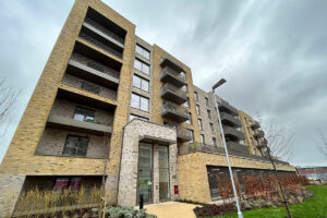
Relevant Case Studies

Speak to one of our experts today